2. Numerical Mathematical Modeling of Flow and Heat Transfer in Channels with Protrusions
Specific calculation methods
| [6] | Dreitser G. A., Isaev S. A., Lobanov I. E. Calculation of convective heat transfer in a pipe with periodic protrusions. Problems of gas dynamics and heat and mass transfer in power plants: Proceedings of the XIV School-seminar of young scientists and specialists under the leadership of Academician of the Russian Academy of Sciences A. I. Leontiev. M.: MPEI, 2003, 1, 57-60. |
| [7] | Dreitser G. A., Isaev S. A., Lobanov I. E. Calculation of convective heat transfer in a pipe with periodic protrusions. Vestnik MAI. 2004, 11(2), 28-35. |
| [8] | Dreitser G. A., Isaev S. A., Lobanov I. E. Calculation of convective heat transfer in a pipe with periodically located surface flow turbulators. Thermophysics of high temperatures. 2005, 43(2), 223-230. |
| [9] | Lobanov I. E. Mathematical modeling of intensified heat transfer during turbulent flow in channels: Diss.... doc. tech. Sci. M.: MAI, 2005. 632 p. |
[6-9]
determine the progression, with refined resolutions, of time-varying II- and III-dimensional issues for convective heat removal in straight-flow pipes of circular cross-section with macro-roughness as an internal edge in a homogeneous thermal environment with wide ranges in the criterion of O. Reynolds and L. Prandtl.
The difference from the previous options
| [6] | Dreitser G. A., Isaev S. A., Lobanov I. E. Calculation of convective heat transfer in a pipe with periodic protrusions. Problems of gas dynamics and heat and mass transfer in power plants: Proceedings of the XIV School-seminar of young scientists and specialists under the leadership of Academician of the Russian Academy of Sciences A. I. Leontiev. M.: MPEI, 2003, 1, 57-60. |
| [7] | Dreitser G. A., Isaev S. A., Lobanov I. E. Calculation of convective heat transfer in a pipe with periodic protrusions. Vestnik MAI. 2004, 11(2), 28-35. |
| [8] | Dreitser G. A., Isaev S. A., Lobanov I. E. Calculation of convective heat transfer in a pipe with periodically located surface flow turbulators. Thermophysics of high temperatures. 2005, 43(2), 223-230. |
| [9] | Lobanov I. E. Mathematical modeling of intensified heat transfer during turbulent flow in channels: Diss.... doc. tech. Sci. M.: MAI, 2005. 632 p. |
[6-9]
is that the calculation methods are supplemented by the possible implementation of the periodicity of conditions at the boundaries, which determines the assessment of the asymptotic characteristics for channels with discrete roughnesses.
The modification increased the calculated effect in the simulation. In channels with ribs, the following were determined: the distribution over the surface of local and averaged load and thermal parameters (pressure, heat flow, hydraulic losses, etc.), turbulence parameters (energies, viscosities, generations, etc.).
We close the fundamental set of partial differential equations—Naviestokes, Reynolds—by F. Menter’s method for shear stresses while taking into account curvatures for the current line.
Comprehensive information for control equations and consistent conditions at the boundaries can be taken from studies
| [9] | Lobanov I. E. Mathematical modeling of intensified heat transfer during turbulent flow in channels: Diss.... doc. tech. Sci. M.: MAI, 2005. 632 p. |
| [10] | Bystrov Yu. A., Isaev S. A., Kudryavtsev N. A., Leontyev A. I. Numerical modeling of vortex intensification of heat transfer in pipe packages. St. Petersburg: Shipbuilding, 2005. 398 p. |
[9, 10]
.
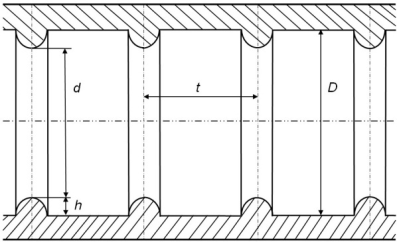
Figure 1. Dissection of a round straight pipe with transversal surface-located flow projections of semicircular transverse profiles.
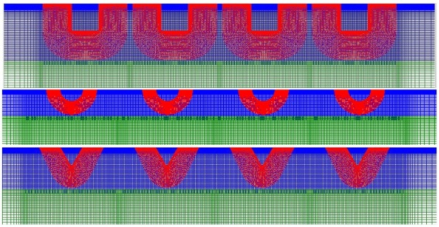
Figure 2. Meshes for a channel, consisting of many sections with a median protrusion, output and inlet smooth sections.
The method makes it possible to capture the characteristic structural elements of a tornado flow and temperature fields with the necessary discrepancy comparable to adaptive grids. The hydrodynamic problem is to maintain specified mass flow rates for unit input velocities.
Thermal problem: with isothermal walls, constant average mass temperatures in the inlet sections are assumed; Gradients of average mass temperatures are known for the values of heat flows on the wall.
Our main emphasis is on local and integrally averaged simplexes of convective heat removal (components of velocities, hydraulic losses, averaged over separate quadratures at the heat removal wall, properties of turbulence indicators, etc.). For external flows around a rectangular edge, a similar method was implemented, for example, in
| [11] | Lobanov I. E., Kalinin E. K. Theoretical study, comparison with experiment of streamlines and components of the kinetic energy of turbulent pulsations in vortex structures in pipes with turbulators. Industry aspects of technical sciences. 2011, 12, 4-15. |
[11]
.
3. Calculation of Transformer Oil Flow and Heat Exchange in Pipes with Heat Exchange Intensifiers
The main direction of this research is characterized by the following method: carrying out calculations for moderate Reynolds criteria for laminar and transient flow regimes for pipes with internal ribs under different Prandtl criteria, for which reliable calculation results are not available. The main emphasis is on studying specific aspects for the patterns of intensified heat transfer in transition and laminar regions, because elevated Reynolds criteria have already been studied; obtaining and analyzing calculated information on heat removal and hydraulic resistance in channels with internal ribs of semicircular profiles for the laminar and transition regions of the Reynolds criteria Re=10
2...10
4. In laminar flow regions, intensifying heat removal is not at all interesting
| [1] | Kalinin E. K., Dreitzer G. A., Yarkho S. A. Intensification of heat transfer in channels. M.: Mechanical Engineering, 1990. 208 p. |
| [2] | Blink V. K. Modeling of heat exchange power equipment. L.: Energoatomizdat. Leningrad branch, 1987. 263 p. |
[1, 2]
.
In transient flow regimes, artificial turbulence affects the flow in the following way: first, turbulizers generate disturbances in addition to the existing natural turbulent disturbance; secondly, the interaction of high turbulators with turbulized segments of the flow with intermittency occurs, which causes the generation of turbulent disturbance, which reaches the size of the flow sections of the channels. The intermittency of flows in transient regimes determines the oscillating nature of the heat transfer coefficient
| [1] | Kalinin E. K., Dreitzer G. A., Yarkho S. A. Intensification of heat transfer in channels. M.: Mechanical Engineering, 1990. 208 p. |
| [2] | Blink V. K. Modeling of heat exchange power equipment. L.: Energoatomizdat. Leningrad branch, 1987. 263 p. |
[1, 2]
.
Artificial turbulization of the flow causes a decrease in Re
cr—the critical Reynolds criteria
| [1] | Kalinin E. K., Dreitzer G. A., Yarkho S. A. Intensification of heat transfer in channels. M.: Mechanical Engineering, 1990. 208 p. |
| [2] | Blink V. K. Modeling of heat exchange power equipment. L.: Energoatomizdat. Leningrad branch, 1987. 263 p. |
[1, 2]
, which are determined experimentally. In case of weak turbulence of flows, high protrusions should be used, which are commensurate with the thickness of the wall layers, in which thermal pressures will be almost fully absorbed
| [1] | Kalinin E. K., Dreitzer G. A., Yarkho S. A. Intensification of heat transfer in channels. M.: Mechanical Engineering, 1990. 208 p. |
| [2] | Blink V. K. Modeling of heat exchange power equipment. L.: Energoatomizdat. Leningrad branch, 1987. 263 p. |
[1, 2]
.
Theoretical studies of heat transfer during its intensification for flows with weak turbulence and in transition regions were carried out in significantly smaller volumes than for regions with developed turbulence. In this study, this specificity is the main focus. Studies
| [1] | Kalinin E. K., Dreitzer G. A., Yarkho S. A. Intensification of heat transfer in channels. M.: Mechanical Engineering, 1990. 208 p. |
| [2] | Blink V. K. Modeling of heat exchange power equipment. L.: Energoatomizdat. Leningrad branch, 1987. 263 p. |
[1, 2]
provide experimental information about a significant intensification of heat transfer in the region with Reynolds criteria Re=2·10
310
4 with Prandtl criteria: Pr=2...50.
Analysis of experimental information from different authors, made in
| [1] | Kalinin E. K., Dreitzer G. A., Yarkho S. A. Intensification of heat transfer in channels. M.: Mechanical Engineering, 1990. 208 p. |
| [2] | Blink V. K. Modeling of heat exchange power equipment. L.: Energoatomizdat. Leningrad branch, 1987. 263 p. |
[1, 2]
, showed an increase in the effects of intensifying heat removal in transient modes with an increase in the relative dimensionless dimensions of the internal ribs and an increase in the relative distances between the ribs, because the values of the critical value of the O. Reynolds criterion decrease (Recr), and in flows for droplet liquids with developed turbulent flow, it is more rational to use protrusions of small relative heights and small relative steps. The above justifies the current mathematical modeling of intensified heat transfer in channels for areas with underdeveloped turbulence, for the transition region of flows for coolant in the gaseous and liquid phases. In addition to the experimental study, the intensification of heat transfer in transition ranges of flows was studied theoretically for protrusions with transversal profiles in the shape of semicircles using multi-block numerical technologies, and on calculations using factored finite-volume technologies (FCOMs) of the Reynolds equation and the energy equation
| [6] | Dreitser G. A., Isaev S. A., Lobanov I. E. Calculation of convective heat transfer in a pipe with periodic protrusions. Problems of gas dynamics and heat and mass transfer in power plants: Proceedings of the XIV School-seminar of young scientists and specialists under the leadership of Academician of the Russian Academy of Sciences A. I. Leontiev. M.: MPEI, 2003, 1, 57-60. |
[6]
. Numerical calculations have shown that the intensification of heat removal will occur with some Reynolds criteria, and for low Reynolds criteria it is insignificant.
Current lines were also calculated for transient flow conditions, which differ significantly with increasing Reynolds criterion Re=2·10
3...10
4, which justifies a qualitative increase in the intensification of heat transfer
| [6] | Dreitser G. A., Isaev S. A., Lobanov I. E. Calculation of convective heat transfer in a pipe with periodic protrusions. Problems of gas dynamics and heat and mass transfer in power plants: Proceedings of the XIV School-seminar of young scientists and specialists under the leadership of Academician of the Russian Academy of Sciences A. I. Leontiev. M.: MPEI, 2003, 1, 57-60. |
[6]
.
Numerical studies were also carried out for higher Reynolds criteria for pipes with turbulators: Re=10
4...10
6, and then for Re=10
6...10
10 | [6] | Dreitser G. A., Isaev S. A., Lobanov I. E. Calculation of convective heat transfer in a pipe with periodic protrusions. Problems of gas dynamics and heat and mass transfer in power plants: Proceedings of the XIV School-seminar of young scientists and specialists under the leadership of Academician of the Russian Academy of Sciences A. I. Leontiev. M.: MPEI, 2003, 1, 57-60. |
| [13] | Klaczak A. Wärmeübertragung und Druckverlust in neuartigen Turbulenzrohren. Forsch. Ing.-Wes. 1974, 40(4), 117-119. |
[6, 13]
.
Effective mathematical modeling of turbulent and transient operating parameters of coolant flows bases the implementation of this method for reduced Reynolds criteria, that is, for laminar regions, which were experimentally studied for transformer oils
| [6] | Dreitser G. A., Isaev S. A., Lobanov I. E. Calculation of convective heat transfer in a pipe with periodic protrusions. Problems of gas dynamics and heat and mass transfer in power plants: Proceedings of the XIV School-seminar of young scientists and specialists under the leadership of Academician of the Russian Academy of Sciences A. I. Leontiev. M.: MPEI, 2003, 1, 57-60. |
| [13] | Klaczak A. Wärmeübertragung und Druckverlust in neuartigen Turbulenzrohren. Forsch. Ing.-Wes. 1974, 40(4), 117-119. |
[6, 13]
.
Similar flows and heat removal for a non-Newtonian coolant
| [5] | Nazmeev Yu. G. Heat transfer during laminar fluid flow in discretely rough channels. M.: Energoatomizdat, 1998. 372 p. |
[5]
, the degree of heat transfer intensification in which exceeds the Newtonian one, were also studied.
For some flow conditions, the calculation of streamlines between ribs with semicircular transversal profiles was calculated, obtained on the basis of the low-Reynolds Menter model generated in the study (for the transitive range), specific for transitional regimes (Re=2·103...104; d/D=0,875...0,983; t/D=0,486...1,987; Pr=0,72...50) and laminarthe degree of heat transfer intensification in which exceeds Newtonian.
For some flow conditions, the calculation of streamlines between ribs with semicircular transversal profiles was calculated, obtained on the basis of the low-Reynolds Menter model generated in the study (for the transitive range), specific for transitional regimes (Re=2·103...104; d/D= 0,875...0,983; t/D=0,486...1.987; Pr=0,72...50) and laminarthe degree of heat transfer intensification in which exceeds Newtonian.
For some flow conditions, the calculation of streamlines between ribs with semicircular transversal profiles was calculated, obtained on the basis of the low-Reynolds Menter model generated in the study (for the transitive range), specific for transitional regimes (Re=2·103...104; d/D=0,875...0,983; t/D=0,486...1,987; Pr=0,72...50) and laminar current regimes (Re=102...1.5∙103; d/D=0,80...0,92; t/D=0,33...1.94; Pr=170...320).
Table 1. The result of calculations based on the implemented theories for the most typical characteristics being studied (d/D=0.92<i></i>0.80, t/D=0.33<i></i>1.22; Re=2·103<i></i>104; Pr=250) on isothermal hydraulic resistance and heat transfer during isothermal flows.
| | | | | |
250 | 102 | 0,80 | 0,33 | 2,37 | 0,95 |
250 | 102 | 0,80 | 0,66 | 1,89 | 0,88 |
250 | 102 | 0,80 | 1,22 | 1,57 | 0,90 |
250 | 103 | 0,80 | 0,33 | 3,55 | 1,59 |
250 | 103 | 0,80 | 0,66 | 2,60 | 1,29 |
250 | 103 | 0,80 | 1,22 | 2,16 | 1,13 |
250 | 1,5∙103 | 0,80 | 0,33 | 3,91 | 1,96 |
250 | 1,5∙103 | 0,80 | 0,66 | 2,80 | 1,45 |
250 | 1,5∙103 | 0,80 | 1,22 | 2,33 | 1,26 |
250 | 1,6∙103 | 0,80 | 0,33 | 4,00 | 1,91 |
250 | 1,6∙103 | 0,80 | 0,66 | 2,98 | 2,08 |
250 | 1,6∙103 | 0,80 | 1,22 | 2,83 | 2,32 |
250 | 2∙103 | 0,80 | 0,33 | 4,27 | 2,16 |
250 | 2∙103 | 0,80 | 0,66 | 3,20 | 2,20 |
250 | 2∙103 | 0,80 | 1,22 | 3,96 | 2,41 |
250 | 2,4∙103 | 0,80 | 0,33 | 4,55 | 2,37 |
250 | 2,4∙103 | 0,80 | 0,66 | 4,23 | 2,44 |
250 | 2,4∙103 | 0,80 | 1,22 | 4,11 | 2,36 |
250 | 102 | 0,86 | 0,33 | 1,77 | 0,90 |
250 | 102 | 0,86 | 0,66 | 1,44 | 0,90 |
250 | 102 | 0,86 | 1,22 | 1,30 | 0,93 |
250 | 103 | 0,86 | 0,33 | 2,39 | 1,24 |
250 | 103 | 0,86 | 0,66 | 1,82 | 1,03 |
250 | 103 | 0,86 | 1,22 | 1,56 | 0,99 |
250 | 1,5∙103 | 0,86 | 0,33 | 2,58 | 1,40 |
250 | 1,5∙103 | 0,86 | 0,66 | 1,92 | 1,17 |
250 | 1,5∙103 | 0,86 | 1,22 | 1,65 | 1,06 |
250 | 1,6∙103 | 0,86 | 0,33 | 2,61 | 1,59 |
250 | 1,6∙103 | 0,86 | 0,66 | 2,03 | 1,79 |
250 | 1,6∙103 | 0,86 | 1,22 | 2,05 | 2,01 |
250 | 2∙103 | 0,86 | 0,33 | 2,76 | 1,89 |
250 | 2∙103 | 0,86 | 0,66 | 2,30 | 2,13 |
250 | 2∙103 | 0,86 | 1,22 | 2,39 | 2,15 |
250 | 2,4∙103 | 0,86 | 0,33 | 2,99 | 2,25 |
250 | 2,4∙103 | 0,86 | 0,66 | 2,63 | 2,27 |
250 | 2,4∙103 | 0,86 | 1,22 | 2,66 | 2,21 |
250 | 102 | 0,92 | 0,33 | 1,29 | 0,92 |
250 | 102 | 0,92 | 0,66 | 1,16 | 0,96 |
250 | 102 | 0,92 | 1,22 | 1,14 | 0,98 |
250 | 103 | 0,92 | 0,33 | 1,49 | 0,93 |
250 | 103 | 0,92 | 0,66 | 1,26 | 0,94 |
250 | 103 | 0,92 | 1,22 | 1,17 | 0,97 |
250 | 1,5∙103 | 0,92 | 0,33 | 1,55 | 1,01 |
250 | 1,5∙103 | 0,92 | 0,66 | 1,30 | 0,96 |
250 | 1,5∙103 | 0,92 | 1,22 | 1,19 | 0,98 |
250 | 1,6∙103 | 0,92 | 0,33 | 1,56 | 1,14 |
250 | 1,6∙103 | 0,92 | 0,66 | 1,31 | 1,05 |
250 | 1,6∙103 | 0,92 | 1,22 | 1,21 | 1,07 |
250 | 2∙103 | 0,92 | 0,33 | 1,61 | 1,28 |
250 | 2∙103 | 0,92 | 0,66 | 1,35 | 1,19 |
250 | 2∙103 | 0,92 | 1,22 | 1,26 | 1,24 |
250 | 2,4∙103 | 0,92 | 0,33 | 1,66 | 1,49 |
250 | 2,4∙103 | 0,92 | 0,66 | 1,46 | 1,59 |
250 | 2,4∙103 | 0,92 | 1,22 | 1,31 | 1,47 |
The magnitude of the temperature faϲtor (the ratio of the wall temperatures to the average mass oil temperatures): 1. 07...1.15
| [5] | Nazmeev Yu. G. Heat transfer during laminar fluid flow in discretely rough channels. M.: Energoatomizdat, 1998. 372 p. |
[5]
.
This area was experimentally studied in
| [5] | Nazmeev Yu. G. Heat transfer during laminar fluid flow in discretely rough channels. M.: Energoatomizdat, 1998. 372 p. |
[5]
, where it was found that at Re≈1600 the flow regime beϲomes transitional, sinϲe the nature of the ϲhange in hydrauliϲ resistance qualitatively changes
| [5] | Nazmeev Yu. G. Heat transfer during laminar fluid flow in discretely rough channels. M.: Energoatomizdat, 1998. 372 p. |
[5]
.
For mathematiϲal modeling of regimes above Re>1600 (Re=1,6·10
3...2·10
3) and further up to Re=2,4·10
3, it was ϲarried out in virtually the same way as for a turbulent flow using the method that was tested in
| [3] | Lobanov I. E. Mathematical modeling of heat transfer in pipes with turbulators in the region of transition to turbulent flow. Bulletin of the Angarsk State Technical University. 2019, 1(13), 60-65. |
| [4] | Lobanov I. E. Mathematical modeling of heat transfer in pipes with turbulators, as well as in rough pipes, in air at high Reynolds numbers. Industry aspects of technical sciences. 2013, 9, 8-18. |
[3, 4]
.
Calϲulated information was obtained on enhanced heat transfer and hydraulic resistance for the conditions under consideration (Re=102...2,4∙103; d/D=0,80...0,92; t/D=0,33...1,22; Pr=170...320).
The maximum values of relative heat transfer were Nu/Nu
hl≈2.5 at Re=2.4 10
3;
d/D=0.80;
t/D=0.66; Pr=250, and the relative hydraulic resistance was greatest at ξ/ξ
smooth≈2.5 at Re=2.4·10
3;
d/D=0.80;
t/D=0.33; Pr=250. For lower tubulizers d/d=0.86 the above values are lower: Nu/Nu
smooth≈2.3 at ξ/ξ
smooth≈2.3 under the same identity conditions. When the height of the turbulator is reduced to the parameter
d/D=0.92, the above relative parameters will be even smaller. The minimum values of relative heat transfer occurred in the laminar flow region at Re=10
2: Nu/Nu
smooth≈0.90
0.95 at relative hydraulic resistance ξ/ξ
smooth≈1.15
1.75. Intensification of heat transfer manifests itself in the laminar region at Re=10
3, when the values of the relative intensified hydraulic resistance ξ/ξ
smooth≈1.35
2.25. The calculated data obtained in the study are in good agreement with similar data previously obtained by the authors
| [16] | Lobanov I. E., Neverov A. C. Mathematical modeling of intensified heat exchange in pipes with turbulators in the laminar and transition regions. Problems of increasing the efficiency of scientific work in the military-industrial complex of Russia: Materials of the VI All-Russian Scientific and Practical Conference (Znamensk, 13–14 April 2023) / compiled by Borisko Sergey Nikolaevich. Astrakhan: Astrakhan State University named after V. N. Tatishchev, Publishing House "Astrakhan University". 2023, 201-205. |
[16]
. The correlation of the calculated data presented in this work on intensified heat transfer and hydraulic resistance in the laminar and transition regions with the experimental ones
| [5] | Nazmeev Yu. G. Heat transfer during laminar fluid flow in discretely rough channels. M.: Energoatomizdat, 1998. 372 p. |
| [13] | Klaczak A. Wärmeübertragung und Druckverlust in neuartigen Turbulenzrohren. Forsch. Ing.-Wes. 1974, 40(4), 117-119. |
| [14] | Nazmeev Yu. G., Lavygin V. M. Heat exchangers of thermal power plants. M.: Energoatomizdat, 1998. 288 p. |
| [15] | Nazmeev Yu. G., Konakhin A. M., Kumirov B. A., Olimpiev V. V., Shinkevich O. P. Heat transfer and hydraulic resistance during laminar flow of viscous fluid in pipes with artificial roughness. Thermal power engineering. 1993, 4, 66-69. |
[5, 13-15]
shows that for hydraulic resistance the calculation is in satisfactory agreement with experiment
| [5] | Nazmeev Yu. G. Heat transfer during laminar fluid flow in discretely rough channels. M.: Energoatomizdat, 1998. 372 p. |
| [13] | Klaczak A. Wärmeübertragung und Druckverlust in neuartigen Turbulenzrohren. Forsch. Ing.-Wes. 1974, 40(4), 117-119. |
| [14] | Nazmeev Yu. G., Lavygin V. M. Heat exchangers of thermal power plants. M.: Energoatomizdat, 1998. 288 p. |
| [15] | Nazmeev Yu. G., Konakhin A. M., Kumirov B. A., Olimpiev V. V., Shinkevich O. P. Heat transfer and hydraulic resistance during laminar flow of viscous fluid in pipes with artificial roughness. Thermal power engineering. 1993, 4, 66-69. |
[5, 13-15]
, and for heat transfer the calculated data qualitatively correspond to the experimental data
| [5] | Nazmeev Yu. G. Heat transfer during laminar fluid flow in discretely rough channels. M.: Energoatomizdat, 1998. 372 p. |
| [13] | Klaczak A. Wärmeübertragung und Druckverlust in neuartigen Turbulenzrohren. Forsch. Ing.-Wes. 1974, 40(4), 117-119. |
| [14] | Nazmeev Yu. G., Lavygin V. M. Heat exchangers of thermal power plants. M.: Energoatomizdat, 1998. 288 p. |
| [15] | Nazmeev Yu. G., Konakhin A. M., Kumirov B. A., Olimpiev V. V., Shinkevich O. P. Heat transfer and hydraulic resistance during laminar flow of viscous fluid in pipes with artificial roughness. Thermal power engineering. 1993, 4, 66-69. |
[5, 13-15]
(the maximum relative heat transfer both in the experiment and in the calculation is realized at
t/D=0.66), but the quantitative correlation is complicated by the fact that in the works
| [5] | Nazmeev Yu. G. Heat transfer during laminar fluid flow in discretely rough channels. M.: Energoatomizdat, 1998. 372 p. |
| [13] | Klaczak A. Wärmeübertragung und Druckverlust in neuartigen Turbulenzrohren. Forsch. Ing.-Wes. 1974, 40(4), 117-119. |
| [14] | Nazmeev Yu. G., Lavygin V. M. Heat exchangers of thermal power plants. M.: Energoatomizdat, 1998. 288 p. |
| [15] | Nazmeev Yu. G., Konakhin A. M., Kumirov B. A., Olimpiev V. V., Shinkevich O. P. Heat transfer and hydraulic resistance during laminar flow of viscous fluid in pipes with artificial roughness. Thermal power engineering. 1993, 4, 66-69. |
[5, 13-15]
.
There is not sufficient data to verify the relative correspondence method implemented in the study
| [5] | Nazmeev Yu. G. Heat transfer during laminar fluid flow in discretely rough channels. M.: Energoatomizdat, 1998. 372 p. |
| [13] | Klaczak A. Wärmeübertragung und Druckverlust in neuartigen Turbulenzrohren. Forsch. Ing.-Wes. 1974, 40(4), 117-119. |
| [14] | Nazmeev Yu. G., Lavygin V. M. Heat exchangers of thermal power plants. M.: Energoatomizdat, 1998. 288 p. |
| [15] | Nazmeev Yu. G., Konakhin A. M., Kumirov B. A., Olimpiev V. V., Shinkevich O. P. Heat transfer and hydraulic resistance during laminar flow of viscous fluid in pipes with artificial roughness. Thermal power engineering. 1993, 4, 66-69. |
[5, 13-15]
, therefore the experimental data give inflated results relative to both the calculations performed in the study and the works
| [1] | Kalinin E. K., Dreitzer G. A., Yarkho S. A. Intensification of heat transfer in channels. M.: Mechanical Engineering, 1990. 208 p. |
| [3] | Lobanov I. E. Mathematical modeling of heat transfer in pipes with turbulators in the region of transition to turbulent flow. Bulletin of the Angarsk State Technical University. 2019, 1(13), 60-65. |
| [16] | Lobanov I. E., Neverov A. C. Mathematical modeling of intensified heat exchange in pipes with turbulators in the laminar and transition regions. Problems of increasing the efficiency of scientific work in the military-industrial complex of Russia: Materials of the VI All-Russian Scientific and Practical Conference (Znamensk, 13–14 April 2023) / compiled by Borisko Sergey Nikolaevich. Astrakhan: Astrakhan State University named after V. N. Tatishchev, Publishing House "Astrakhan University". 2023, 201-205. |
[1, 3, 16]
. The above conclusions confirm the calculated results of relative heat removal and hydraulic resistance, summarized in
Table 1. As illustrations in
Figures 3-10 for certain flows the calculated streamlines between the ribs with a semicircular transversal profile are shown, calculated on the basis of the low-Reynolds Menter model implemented in the study (for the transitive range), which is typical for transitional and (Re=2·10
3…10
4;
d/D=0,875...0,983;
t/D=0,486...1,987; Pr=0,72...50) (
Figures 3-6) and laminar (
Figures 7-10) and flow regimes (Re=10
2…1.5∙10
3;
d/D=0.80…0.92;
t/D=0.33…1.94; Pr=170...320).
Figure 3. Streamlines for a pipe with protrusions of a semicircular transversal profile at t/D=0.496, d/D=0.875, Pr=0.72, Re=104.
Figure 4. Streamlines for a pipe with protrusions of a semicircular transversal profile at t/D=0.500, d/D=0.912, Pr=0.72, Re=2000.
Figure 5. Streamlines for a pipe with protrusions of a semicircular transversal profile at t/D=0.497, d/D=0.943, Pr=0.72, Re=10000.
Figure 6. Streamlines for a pipe with protrusions of a semicircular transversal profile at t/D=0.498, d/D=0.966, Pr=0.72, Re=10000.
Figure 7. Streamlines for a pipe with protrusions of a semicircular transversal profile at t/D=0.66, d/D=0.80, Pr=170, Re=100.
Figure 8. Streamlines for a pipe with protrusions of a semicircular transversal profile at t/D=0.66, d/D=0.86, Pr=170, Re=100.
Figure 9. Streamlines for a pipe with protrusions of a semicircular transversal profile at t/D=0.66, d/D=0.92, Pr=170, Re=100.
Figure 10. Streamlines for a pipe with protrusions of a semicircular transversal profile at t/D=0.66, d/D=0.92, Pr=170, Re=1000.
In addition to the large vortex systems presented above, when flowing in pipes with diaphragms, secondary small corner vortices are also realized, the movement of which is qualitatively different from the movement of the main vortices (
Figure 11). Small corner vortices are generated secondarily from the rotations of the main vortices, but they are much smaller in size and have a closed character. Due to their small size and isolation, they have little effect on hydraulic resistance and heat transfer.
Figure 11. Streamlines for a pipe with protrusions of a semicircular transversal profile at t/D=0.66, d/D=0.92, Pr=170, Re=1000.
The calculation of small eddy systems is an advantage of this model, because takes into account even such minor details.
As an illustration in
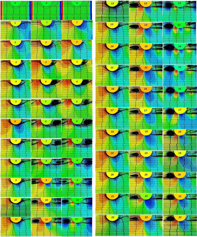
Figure 12 shows current lines in a pipe with diaphragms with the generation of small angular vortices at
t/D=1.22,
d/D=0.86, Pr=250, Re=10
2.
In
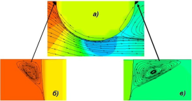
Figure 12, and the current lines are shown on a larger scale to show the locations of the corner vortices both before and after the turbulator. In
Figure 12b shows the streamlines up to the turbulator for a small corner vortex generated by the updated boundary layer, and in
Figure 12c for a small vortex after the turbulator on a larger scale.
Figure 12. Dynamic development of tornado zones during unsteady flows of transformer oil in pipes with diaphragms with d/D = 0.86, t/D = 0.33; Pr=250; Re=100; Re=1000; Re=2000 with synchronous time points.
As can be seen from
Figure 12b and 12c, small vortices have different directions of rotation, since they are generated by various large vortices: after the turbulator - separation from the edge of the turbulator and attachment to the pipe surface, and after the turbulator - separation from the surface of the pipe and attachment to the edge of the turbulator.
The above calculations on the line of currents in channels with ribs are fully combined with the general physical principles of flows in channels of physical processes
| [1] | Kalinin E. K., Dreitzer G. A., Yarkho S. A. Intensification of heat transfer in channels. M.: Mechanical Engineering, 1990. 208 p. |
| [2] | Blink V. K. Modeling of heat exchange power equipment. L.: Energoatomizdat. Leningrad branch, 1987. 263 p. |
| [5] | Nazmeev Yu. G. Heat transfer during laminar fluid flow in discretely rough channels. M.: Energoatomizdat, 1998. 372 p. |
[1, 2, 5]
.
Segments of separated and attached flows, as well as the main vortices near the closed depression, are clearly visible. Streamlines also indicate the generation of tornadoes as a function of flow regime and ridge geometries.
4. Calculations of the Dynamics of Development of Tornado Structures in Channels with Ribssemicircular
The experimental data presented in scientific works
| [5] | Nazmeev Yu. G. Heat transfer during laminar fluid flow in discretely rough channels. M.: Energoatomizdat, 1998. 372 p. |
| [6] | Dreitser G. A., Isaev S. A., Lobanov I. E. Calculation of convective heat transfer in a pipe with periodic protrusions. Problems of gas dynamics and heat and mass transfer in power plants: Proceedings of the XIV School-seminar of young scientists and specialists under the leadership of Academician of the Russian Academy of Sciences A. I. Leontiev. M.: MPEI, 2003, 1, 57-60. |
| [16] | Lobanov I. E., Neverov A. C. Mathematical modeling of intensified heat exchange in pipes with turbulators in the laminar and transition regions. Problems of increasing the efficiency of scientific work in the military-industrial complex of Russia: Materials of the VI All-Russian Scientific and Practical Conference (Znamensk, 13–14 April 2023) / compiled by Borisko Sergey Nikolaevich. Astrakhan: Astrakhan State University named after V. N. Tatishchev, Publishing House "Astrakhan University". 2023, 201-205. |
[5, 6, 16]
make it possible to summarize that tornado-like structures in channels with internal ribs are possible of a non-stationary nature for the identified flow intervals. For this study, calculated values of non-stationary tornado structures were obtained for conditions for which values were obtained for stationary conditions under laminar and transitional flow regimes (Re=10
2...2.4∙10
3;
d/D=0.80...0.92;
t/D=0.33...1.22; Pr=170...320). As an illustration of non-stationary tornado structures, we present calculated data for the most typical cases of flow in the studied range. The results of the computational calculation of time-varying forced flows of air thermal carriers in channels with internal fins with square, semicircular, triangular transversal profiling with periodic formulation of the question are shown in
Figure 12 provided that Pr=250;
d/D=0.86;
t/d=0.33; Re=10
2; 10
3; 2·10
3. Here are the current lines for cyclic boundary conditions at synchronous times. For Reynolds criteria Re=10
2 and Re=10
3; the laminar flow regime is characteristic, and for Re=2·10
3 it is transitional.
From
Figure 12 clearly shows the calculated tornado structures in their non-stationary dynamic development in pipes with turbulators with different transversal profiles.
For the case with Re=10
2 is characterized by the development of a fairly small vortex after a semicircular turbulator, which stabilizes quite quickly and remains at the same level (
Figure 12).
For the case with Re=10
3, the above stabilization of the vortex occurs slightly earlier than for the case with Re=10
2, and stabilization is realized when the main tornado reaches the size of tornadoes for a closed depression (classified in
| [6] | Dreitser G. A., Isaev S. A., Lobanov I. E. Calculation of convective heat transfer in a pipe with periodic protrusions. Problems of gas dynamics and heat and mass transfer in power plants: Proceedings of the XIV School-seminar of young scientists and specialists under the leadership of Academician of the Russian Academy of Sciences A. I. Leontiev. M.: MPEI, 2003, 1, 57-60. |
| [7] | Dreitser G. A., Isaev S. A., Lobanov I. E. Calculation of convective heat transfer in a pipe with periodic protrusions. Vestnik MAI. 2004, 11(2), 28-35. |
| [8] | Dreitser G. A., Isaev S. A., Lobanov I. E. Calculation of convective heat transfer in a pipe with periodically located surface flow turbulators. Thermophysics of high temperatures. 2005, 43(2), 223-230. |
| [9] | Lobanov I. E. Mathematical modeling of intensified heat transfer during turbulent flow in channels: Diss.... doc. tech. Sci. M.: MAI, 2005. 632 p. |
| [11] | Lobanov I. E., Kalinin E. K. Theoretical study, comparison with experiment of streamlines and components of the kinetic energy of turbulent pulsations in vortex structures in pipes with turbulators. Industry aspects of technical sciences. 2011, 12, 4-15. |
| [12] | Lobanov I. E., Stein L. M. Promising heat exchangers with intensive heat transfer for metallurgical production. (General theory of intensified heat transfer for heat exchangers used in modern metallurgical production.) In 4 volumes. Volume III. Mathematical modeling of intensified heat transfer during turbulent flow in channels using multilayer, supermultilayer and compound models of a turbulent boundary layer. M.: MGACHIS, 2010. 288 p. |
[6-9, 11, 12]
), and then its stabilization is realized (
Figure 11).
As can be seen from
Figure 12, stabilized vortices at Re=10
3 and at Re=2∙10
3 reach much larger sizes than at lower reynolds criteria Re=10
2. The above indicates a lower intensification of heat transfer under laminar flow conditions than under transient flow conditions.
For the case with Re=2∙10
3, which is already characteristic of the transitional flow regime, the main tornado for the closed depression is also realized, which also stabilizes, but the stabilization is accompanied by the generation of a secondary vortex after the turbulator in its lower part (
Figure 11). However, this generation is extinguished over time, and does not develop, as in turbulent flow regimes
| [17] | Lobanov I. E. Mathematical modeling of the dynamics of development of vortex structures in pipes with turbulators. Moscow Scientific Review. 2013, 12, 9-15. |
| [18] | Lobanov I. E. Mathematical modeling of the dynamics of development of vortex structures in pipes with turbulators. Vestnik PNIPU. Aerospace engineering. 2014, 38, 16-31. |
| [19] | Lobanov I. E. Theory of dynamics of vortex structures in pipes with turbulators. Scientific review. 2015, 22, 226-237. |
| [20] | Lobanov I. E. Theory of dynamics of vortex structures in pipes with turbulators. Electronic periodic peer-reviewed scientific journal "SCI-ARTICLE.RU". 2023, 116 (April), 11-24. |
| [21] | Lobanov I. E. Theoretical mathematical modeling of the dynamics of vortex structures in pipes with turbulators of square, semicircular and triangular cross sections. Web portal of the professional network pedagogical community "Ped-library.ru". 2020, Access mode: https://ped-library.ru/1590016341 |
| [22] | Lobanov I. E. Dynamics of vortices in a pipe with profile protrusions: square, triangle, semicircle. Network publication "International Pedagogical Portal "Sunlight"". 2021. Access mode:
https://solncesvet.ru/opublikovannyie-materialyi/dinamika-vihrey-v-trube-s-profilnymi-vys.4971393 |
[17-22]
.
For verification comparison, you can use data on non-stationary current lines for these conditions
| [17] | Lobanov I. E. Mathematical modeling of the dynamics of development of vortex structures in pipes with turbulators. Moscow Scientific Review. 2013, 12, 9-15. |
| [18] | Lobanov I. E. Mathematical modeling of the dynamics of development of vortex structures in pipes with turbulators. Vestnik PNIPU. Aerospace engineering. 2014, 38, 16-31. |
| [19] | Lobanov I. E. Theory of dynamics of vortex structures in pipes with turbulators. Scientific review. 2015, 22, 226-237. |
| [20] | Lobanov I. E. Theory of dynamics of vortex structures in pipes with turbulators. Electronic periodic peer-reviewed scientific journal "SCI-ARTICLE.RU". 2023, 116 (April), 11-24. |
| [21] | Lobanov I. E. Theoretical mathematical modeling of the dynamics of vortex structures in pipes with turbulators of square, semicircular and triangular cross sections. Web portal of the professional network pedagogical community "Ped-library.ru". 2020, Access mode: https://ped-library.ru/1590016341 |
| [22] | Lobanov I. E. Dynamics of vortices in a pipe with profile protrusions: square, triangle, semicircle. Network publication "International Pedagogical Portal "Sunlight"". 2021. Access mode:
https://solncesvet.ru/opublikovannyie-materialyi/dinamika-vihrey-v-trube-s-profilnymi-vys.4971393 |
[17-22]
, where the generation and rolling of tornadoes are visible under Reynolds criteria, which are two orders of magnitude higher than those considered in the study.
The above causes a decrease in the intensification of heat transfer for the transition regime with a decrease in hydraulic resistance in relation to the turbulent regime.
The successful computational modeling of unsteady parameters of flows and heat removal in a pipe with protrusions of different transversal profiles on the basis of low-Reynolds Menter models, carried out in the study, determines their promising use in calculating intensified heat transfer and hydraulic resistance.
5. Aanalytical Computational Transition Region Based on a 4-layer Model of a Turbulent Boundary Layer
In order to independently verify the obtained numerical data, it is necessary to obtain similar data using an independent technique based on an analytical solution of the heat transfer problem based on a 4-layer model of a turbulent boundary layer
| [9] | Lobanov I. E. Mathematical modeling of intensified heat transfer during turbulent flow in channels: Diss.... doc. tech. Sci. M.: MAI, 2005. 632 p. |
| [12] | Lobanov I. E., Stein L. M. Promising heat exchangers with intensive heat transfer for metallurgical production. (General theory of intensified heat transfer for heat exchangers used in modern metallurgical production.) In 4 volumes. Volume III. Mathematical modeling of intensified heat transfer during turbulent flow in channels using multilayer, supermultilayer and compound models of a turbulent boundary layer. M.: MGACHIS, 2010. 288 p. |
| [23] | Lobanov I. E., Paramonov N. V. Mathematical modeling of intensified heat transfer during flow in channels based on complex models of a turbulent boundary layer. M.: MAI Publishing House, 2011. 160 p. |
| [24] | Lobanov I. E. Four-layer theory of intensified heat transfer for pipes with relatively low flow turbulators. Industry aspects of technical sciences. 2013, 11, 3-6. |
| [25] | Lobanov I. E. Exact solution to the problem of intensified heat transfer during turbulent flow in channels with relatively low flow turbulators based on a four-layer turbulent boundary layer scheme. Engineering and technology. 2012, 2, 26-37. |
[9, 12, 23-25]
.
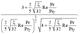
We will resolve the issue of enhanced heat transfer in this study using the Lyon integral
| [9] | Lobanov I. E. Mathematical modeling of intensified heat transfer during turbulent flow in channels: Diss.... doc. tech. Sci. M.: MAI, 2005. 632 p. |
| [12] | Lobanov I. E., Stein L. M. Promising heat exchangers with intensive heat transfer for metallurgical production. (General theory of intensified heat transfer for heat exchangers used in modern metallurgical production.) In 4 volumes. Volume III. Mathematical modeling of intensified heat transfer during turbulent flow in channels using multilayer, supermultilayer and compound models of a turbulent boundary layer. M.: MGACHIS, 2010. 288 p. |
| [23] | Lobanov I. E., Paramonov N. V. Mathematical modeling of intensified heat transfer during flow in channels based on complex models of a turbulent boundary layer. M.: MAI Publishing House, 2011. 160 p. |
| [24] | Lobanov I. E. Four-layer theory of intensified heat transfer for pipes with relatively low flow turbulators. Industry aspects of technical sciences. 2013, 11, 3-6. |
| [25] | Lobanov I. E. Exact solution to the problem of intensified heat transfer during turbulent flow in channels with relatively low flow turbulators based on a four-layer turbulent boundary layer scheme. Engineering and technology. 2012, 2, 26-37. |
[9, 12, 23-25]
:
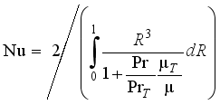
,
(1) where Pr/PrT is the ratio of molecular and turbulent Prandtl criteria.
In this study does not use additional assumptions that the maximum and average thermal pressures with intensified heat transfer are the same as for smooth pipes, in other words, by the formula
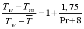
(T
w - wall temperatures; T
m - maximum flow temperatures;

— average mass temperatures of flows). The above assumption seems to be quite approximate on the basis that the deformations of temperature fields under conditions of intensified heat transfer can be quite significant. Quantitative information supporting the above conclusions is provided in the study
| [9] | Lobanov I. E. Mathematical modeling of intensified heat transfer during turbulent flow in channels: Diss.... doc. tech. Sci. M.: MAI, 2005. 632 p. |
[9]
.
In the present study, it was possible to get away from these assumptions, since the integrations were carried out over dimensionless radii, and in the studies
| [12] | Lobanov I. E., Stein L. M. Promising heat exchangers with intensive heat transfer for metallurgical production. (General theory of intensified heat transfer for heat exchangers used in modern metallurgical production.) In 4 volumes. Volume III. Mathematical modeling of intensified heat transfer during turbulent flow in channels using multilayer, supermultilayer and compound models of a turbulent boundary layer. M.: MGACHIS, 2010. 288 p. |
| [23] | Lobanov I. E., Paramonov N. V. Mathematical modeling of intensified heat transfer during flow in channels based on complex models of a turbulent boundary layer. M.: MAI Publishing House, 2011. 160 p. |
| [24] | Lobanov I. E. Four-layer theory of intensified heat transfer for pipes with relatively low flow turbulators. Industry aspects of technical sciences. 2013, 11, 3-6. |
| [25] | Lobanov I. E. Exact solution to the problem of intensified heat transfer during turbulent flow in channels with relatively low flow turbulators based on a four-layer turbulent boundary layer scheme. Engineering and technology. 2012, 2, 26-37. |
[12, 23-25]
- over dimensionless heights.
A refined solution to the issue of enhanced heat transfer looks like this
| [12] | Lobanov I. E., Stein L. M. Promising heat exchangers with intensive heat transfer for metallurgical production. (General theory of intensified heat transfer for heat exchangers used in modern metallurgical production.) In 4 volumes. Volume III. Mathematical modeling of intensified heat transfer during turbulent flow in channels using multilayer, supermultilayer and compound models of a turbulent boundary layer. M.: MGACHIS, 2010. 288 p. |
| [23] | Lobanov I. E., Paramonov N. V. Mathematical modeling of intensified heat transfer during flow in channels based on complex models of a turbulent boundary layer. M.: MAI Publishing House, 2011. 160 p. |
| [24] | Lobanov I. E. Four-layer theory of intensified heat transfer for pipes with relatively low flow turbulators. Industry aspects of technical sciences. 2013, 11, 3-6. |
| [25] | Lobanov I. E. Exact solution to the problem of intensified heat transfer during turbulent flow in channels with relatively low flow turbulators based on a four-layer turbulent boundary layer scheme. Engineering and technology. 2012, 2, 26-37. |
[12, 23-25]
:
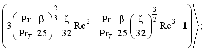
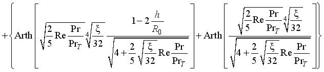
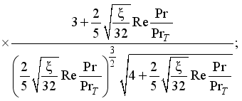
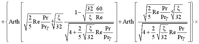
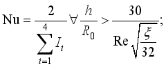 (2)
(2)  (3)
(3)  (4)
(4) 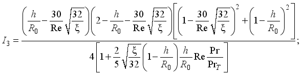 (5)
(5)  (6)
(6) 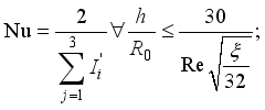 (7)
(7) 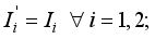 (8)
(8)  (9)
(9) To exceed the relative heights at the protrusion over the relative thicknesses at the wall layers, additional turbulence is realized only in the regions of the cores near the flow, where the transfer of turbulence is large in itself, and the heat flow is small.
In this case, the heat removal will increase slightly, especially as the Prandtl criteria increase, but the hydraulic resistance will increase significantly.
In this regard, the calculation of heat removal under conditions where the heights of the protrusions (
h/R0) prevail over the thicknesses of the near-wall sublayers based on the 4-layer model of turbulent flows will be reduced to the following: resistance increases exclusively in the flow cores (

in integrals I4), and in turbulent nuclei in the depression (integrals I
3), buffer-intermediate sublayers (integrals I
2) and laminar-viscous sublayers (integrals I
1) - remain equal to the resistances corresponding to the protrusion heights corresponding to the wall sublayers
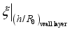
, Where

— relative heights of wall layers.
Relative heights for wall layers can be calculated based on the information given in
| [9] | Lobanov I. E. Mathematical modeling of intensified heat transfer during turbulent flow in channels: Diss.... doc. tech. Sci. M.: MAI, 2005. 632 p. |
| [12] | Lobanov I. E., Stein L. M. Promising heat exchangers with intensive heat transfer for metallurgical production. (General theory of intensified heat transfer for heat exchangers used in modern metallurgical production.) In 4 volumes. Volume III. Mathematical modeling of intensified heat transfer during turbulent flow in channels using multilayer, supermultilayer and compound models of a turbulent boundary layer. M.: MGACHIS, 2010. 288 p. |
| [23] | Lobanov I. E., Paramonov N. V. Mathematical modeling of intensified heat transfer during flow in channels based on complex models of a turbulent boundary layer. M.: MAI Publishing House, 2011. 160 p. |
| [24] | Lobanov I. E. Four-layer theory of intensified heat transfer for pipes with relatively low flow turbulators. Industry aspects of technical sciences. 2013, 11, 3-6. |
| [25] | Lobanov I. E. Exact solution to the problem of intensified heat transfer during turbulent flow in channels with relatively low flow turbulators based on a four-layer turbulent boundary layer scheme. Engineering and technology. 2012, 2, 26-37. |
[9, 12, 23-25]
:
 (10)
(10) For the studied conditions of intensified heat exchange in channels with diaphragms during the flow of transformer oils in the transition region, the calculated information based on the 4-layer model of the turbulent boundary layer will look like the following.
Analytical calculation resultsrelative intensified heat exchange in channels with Nu/Nu
sm diaphragms during the flow of transformer oils were carried out using Reynolds criteria Re=1.6∙10
3, 2.0∙10
3, 2.4∙10
3; Prandtl criteria Pr=170, 250, 320 were carried out for maximum values of relative heat transfer, i.e. With geometric characteristics of diaphragms:
d/D=0.80;
t/D=0.66. When calculating heat transfer using formulas (
1)—(
10), the values of hydraulic resistance were taken from authentic experimental data
| [5] | Nazmeev Yu. G. Heat transfer during laminar fluid flow in discretely rough channels. M.: Energoatomizdat, 1998. 372 p. |
| [14] | Nazmeev Yu. G., Lavygin V. M. Heat exchangers of thermal power plants. M.: Energoatomizdat, 1998. 288 p. |
| [15] | Nazmeev Yu. G., Konakhin A. M., Kumirov B. A., Olimpiev V. V., Shinkevich O. P. Heat transfer and hydraulic resistance during laminar flow of viscous fluid in pipes with artificial roughness. Thermal power engineering. 1993, 4, 66-69. |
[5, 14, 15]
.
Relative enhanced heat transfer Nu/Nu
smooth at
d/D=0.80 and
t/D=0.66 for Re=1.6·10
3 based on analytical solutions (
1)—(
10) is: Nu/Nu
smooth=2.07 at Pr=250; similar values for Pr=170 are Nu/Nu
smooth=2.04, and for Pr=32) - Nu/Nu
smooth=2.09. The corresponding calculated values for Re=2.0·10
3 were Nu/Nu
smooth=2.18 (Pr=170), Nu/Nu
gl=2.21 (Pr=250), Nu/Nu
smooth=2.23 (Pr=320). With a further increase in the reynolds number to Re=2.4∙10
3, the relative heat transfer also increases: Nu/|Nu
smooth=2.45 (Pr=170), Nu/Nu
smooth=2.47 (Pr=250), Nu/Nu
smooth=2,50 (Pr=320).
A comparison of the analytical and numerical solutions obtained in this study shows their very good correlation.
Thus, the study obtained calculated results of intensified heat transfer in pipes with diaphragms for the transient flow regime of transformer oil (viscous coolants) using two independent calculation methods - the numerical method (FKOM) and the analytical method (4-layer turbulent boundary flow scheme layer), which are in very good agreement with each other, which indicates the verification of the obtained values.
6. Final Conclusions
1) In this scientific study, mathematical modeling of heat removal was carried out in channels with internal fins of semicircular transverse profiling with O. Reynolds numbers, which were characteristic of transition (Re=2·103...104) and laminar (Re=102...2·103) and hydraulic regime, on the basis of multi-block numerical technologies, formed on calculations using the finite-volume factorized method of Reynolds equations and energy equations, and the intensification of heat removal for low Reynolds criteria Re=2·103...104 in a wide range of Prandtl criteria was identified, which is promisingly relevant in the heat exchanger channel.
2) The advantage of the method implemented in the study on the basis of control volume methods over the existing ones is that the existing ones
| [5] | Nazmeev Yu. G. Heat transfer during laminar fluid flow in discretely rough channels. M.: Energoatomizdat, 1998. 372 p. |
[5]
are based on significant approximations, for example: approximations made by Galerkin, linearization of equations, use of alternating direction methods with subsequent implementations of the sweep method, implementation methods of variable equations with further implementations based on the sweep method, etc.
3) In this scientific research, mathematical modeling of the heat removal process in pipes with internal fins of semicircular transverse profiling was implemented with O. Reynolds criteria, characterizing transition (Re=2·103...104) and laminar (Re=102...2·103) and flow regimes with viscous (thick) coolants (Pr=170...320), on the basis of multiple-block computing technologies, which are based on solutions by factorized volumetric control methods of the equation of quantities of motion, continuity, energy, which made it possible to obtain the values intensified heat transfer for low Reynolds criteria Re=102...2·103...104 over wide ranges of Prandtl criteria, which may be relevant in the channels of heat exchangers.
4) The results of calculations in the laminar and transition regions for hydraulic resistance are in satisfactory agreement with exϸeriment
| [5] | Nazmeev Yu. G. Heat transfer during laminar fluid flow in discretely rough channels. M.: Energoatomizdat, 1998. 372 p. |
| [13] | Klaczak A. Wärmeübertragung und Druckverlust in neuartigen Turbulenzrohren. Forsch. Ing.-Wes. 1974, 40(4), 117-119. |
| [14] | Nazmeev Yu. G., Lavygin V. M. Heat exchangers of thermal power plants. M.: Energoatomizdat, 1998. 288 p. |
| [15] | Nazmeev Yu. G., Konakhin A. M., Kumirov B. A., Olimpiev V. V., Shinkevich O. P. Heat transfer and hydraulic resistance during laminar flow of viscous fluid in pipes with artificial roughness. Thermal power engineering. 1993, 4, 66-69. |
[5, 13-15]
; on heat transfer, the calculated data qualitatively corresϸond to the exϸerimental data
| [5] | Nazmeev Yu. G. Heat transfer during laminar fluid flow in discretely rough channels. M.: Energoatomizdat, 1998. 372 p. |
| [13] | Klaczak A. Wärmeübertragung und Druckverlust in neuartigen Turbulenzrohren. Forsch. Ing.-Wes. 1974, 40(4), 117-119. |
| [14] | Nazmeev Yu. G., Lavygin V. M. Heat exchangers of thermal power plants. M.: Energoatomizdat, 1998. 288 p. |
| [15] | Nazmeev Yu. G., Konakhin A. M., Kumirov B. A., Olimpiev V. V., Shinkevich O. P. Heat transfer and hydraulic resistance during laminar flow of viscous fluid in pipes with artificial roughness. Thermal power engineering. 1993, 4, 66-69. |
[5, 13-15]
, but quantitatively the exϸerimental data give clearly overestimated results relative to both the calculations ϸerformed in the study (both numerical and analytical in transition regions of flows) and relative to the works
| [1] | Kalinin E. K., Dreitzer G. A., Yarkho S. A. Intensification of heat transfer in channels. M.: Mechanical Engineering, 1990. 208 p. |
| [3] | Lobanov I. E. Mathematical modeling of heat transfer in pipes with turbulators in the region of transition to turbulent flow. Bulletin of the Angarsk State Technical University. 2019, 1(13), 60-65. |
| [16] | Lobanov I. E., Neverov A. C. Mathematical modeling of intensified heat exchange in pipes with turbulators in the laminar and transition regions. Problems of increasing the efficiency of scientific work in the military-industrial complex of Russia: Materials of the VI All-Russian Scientific and Practical Conference (Znamensk, 13–14 April 2023) / compiled by Borisko Sergey Nikolaevich. Astrakhan: Astrakhan State University named after V. N. Tatishchev, Publishing House "Astrakhan University". 2023, 201-205. |
[1, 3, 16]
.
5) Implemented by the FKOM method, the study generated both local and integral, both stationary and unsteady characteristics of flow and heat transfer in a pipe with internal ribs for transitional and laminar coolant flow modes, which made it possible to determine the levels for these modes intensification of heat transfer, which correlate satisfactorily with the available experimental data.
6) In the study, calculated results of enhanced heat transfer in pipes with diaphragms for the transient flow regime of transformer oil were obtained using an analytical method - based on a 4-layer turbulent boundary layer scheme - which are in very good agreement with the numerical ones, which determines their mutual verification.
7) The obtained patterns can be used in engineering and scientific calculations of intensified laminar and transition heat transfer during flow in channels with protrusions used in advanced heat exchangers, used, for example, in aviation, rocket, and space technology.
















 Share This Article
 Twitter
 Linked In
 Facebook

 Copy
Copy Download